Laboratories within the infrastructure
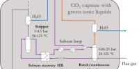
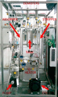
Ionic liquids for CO2 capture
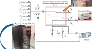
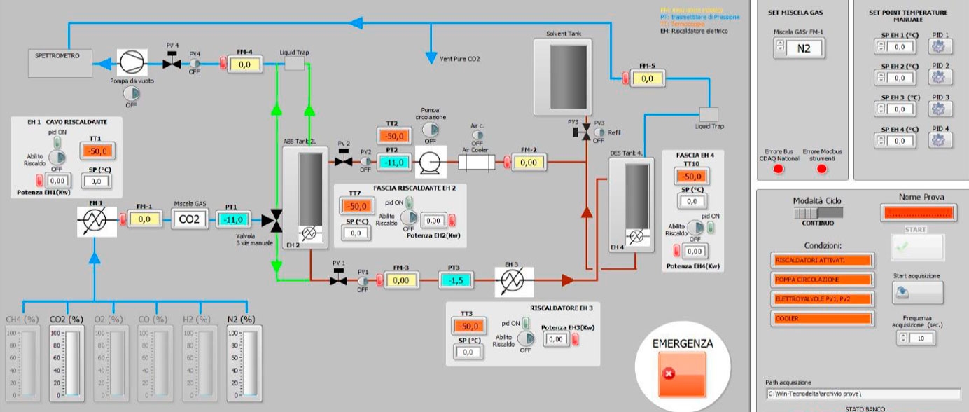
The test station design replicates a traditional two-column scheme for the removal of CO2 from different gas mixtures (N2, O2/H2, CH4, CO). The rig allows the execution of tests in two modes.
- Continuous configuration. CO2absorption occurs in the 2-liter column (p = 1-20 bar; T = 25-65°C): the CO2-poor gas mixture leaves the top of the column and is sampled with a mass spectrometer. The CO2-rich solvent leaving the absorber bottom is heated up (Tmax= 125°C) and flows downwards in the 4-liter desorption column (pmax = 4.5 bar) where CO2 stripped at the column top is sampled. The solvent recirculates back to the absorber through the air cooler and the membrane pump.
- Batch configuration. The absorber is isolated by shut-off valves after filling it with fresh solvent. Gas mixture flows upwards through the solvent until no more CO2is captured (saturation): the column is heated up and eventually depressurized by a vacuum pump (pmin = 0.2 bar) to desorb CO2from the solvent.
Membranes for CO2 capture
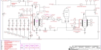
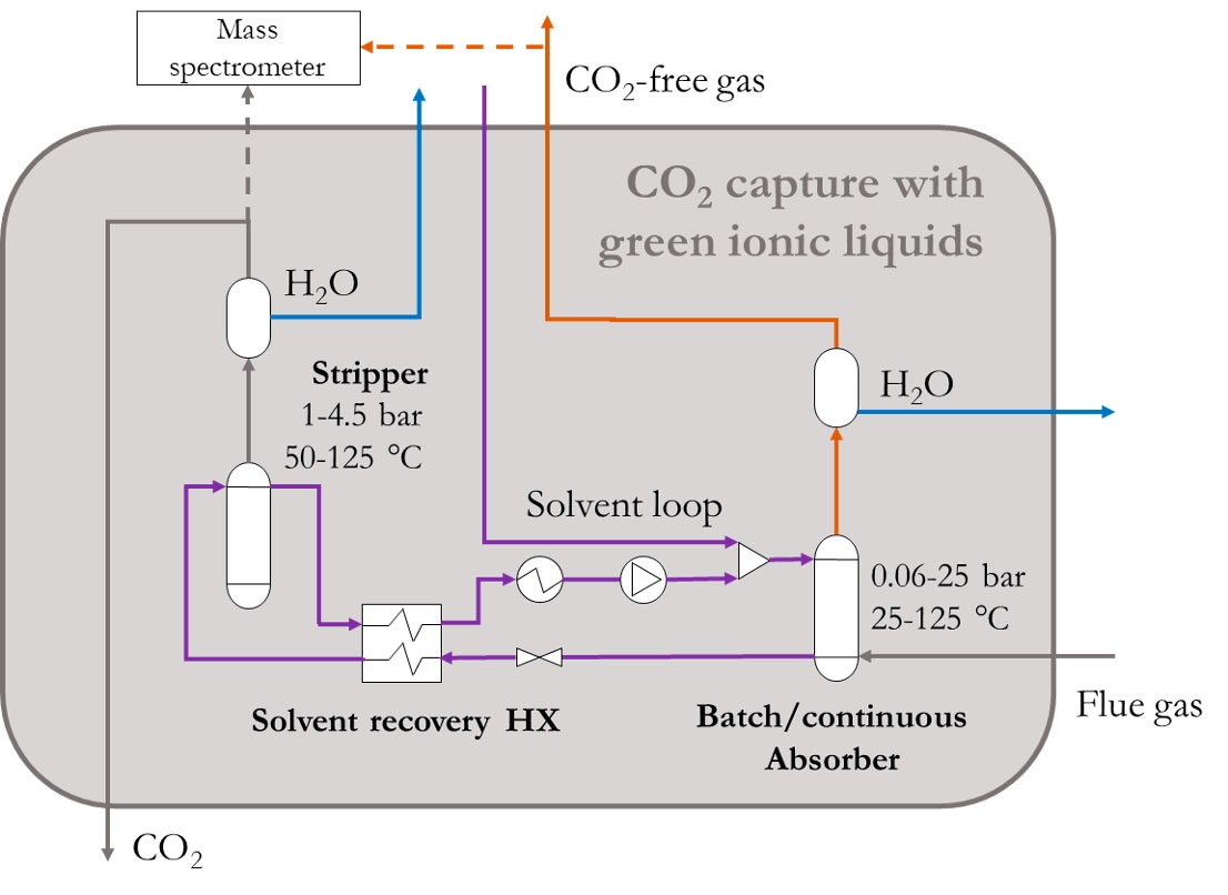
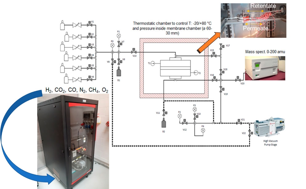
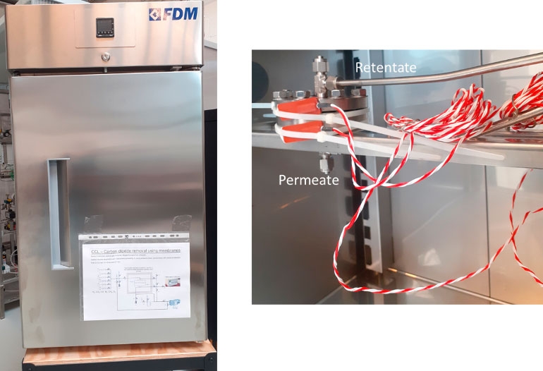
The facility is based on membrane technology and it is used to upgrade biogas (i.e. increasing methane content in natural gas or synthetic natural gas) and as post-combustion capture to sequestrate the CO2 from flue gas. The facility can also be adopted to measure the permeability and selectivity of solid matrices placed in the specifically designed housing. Some parameters can be changed during the test and they are summarized below:
- Gas fraction and composition
- Temperature (-20; +80 °C)
- Pressure (1 atm; 80 bar)
- Relative humidity
Figure 5 shows the schematic diagram of the test station. A gas mixture fills the storage tank B1 until the operating pressure is reached. Successively, the mixture of gases flows into the housing of the membrane at a constant temperature. The permeate is the gas separated from the mixture able to pass through the membrane to the low-pressure environment while the retentate is the remaining part of the original mix. The mass spectrometer guarantees fast analytical gas composition detection in the permeate and retentate.